A few years ago I get the goal to come up with a solution to one unusual situation. One kitchen and two different restaurants, both of them use different POS systems so they are not compatible. The one kitchen prepares meals for both restaurants. There is a need to somehow let to know the waiters in restaurants, that meal is ready to pick up. But at least both restaurants used the same ethernet network. The final product consists of three devices. Two devices with one button to “answer” the call from the kitchen and one unit with two buttons. One for each restaurant.
Goals:
- works on the TCP/IP layer
- small form
- easy to operate by cooks(oily hands) and also require feedback from the restaurant as the waiter is on the way
Electronic and hardware development
Ok, first of all, I create the “proof of concept”. I start with all requirements and start designing the electronic schematic with all required buttons, LED, etc. As the “brain” of the project, I used the ESP8266 NodeMcu board so I was able to use the WiFi to connect to the TCP/IP network. I also added the buzzer to work as an acoustic notification, and the final schematic looks like this.

After that, I connected all on the test board to test all functions and started developing the firmware. It looks like a big mess but you have to believe me it was working.


After the prototyping and development of firmware, I was ready to prepare the PCB. The final PCB was then manufactured at jlcpcb.com and I have to say they provide excellent services.


The development was so fast so I do not have any photos with assembled PCB.
Firmware development
The firmware was split into two versions. One version for the kitchen and one version for each restaurant. The whole concept was simple, the kitchen unit is an HTTP server that is periodically requested from restaurant stations, and with every request, there is also pushing station status to the master unit so there is the required feedback.
Master unit
- start and prepare the HTTP server
- wait for periodical requirest from station units, the request contains the station status(blinking alert, error, etc.)
- if the station misses the periodical request a few times then it is signalized on the master unit as lost, so the kitchen knows exactly if the station unit is working,
- if the button for “call” is pressed then the information is passed in the request response to the station. the LED on the master unit exactly mirrors the status of the station units. If there is an alarm running on the station unit the LED is blinking. After the response (push button on station unit) then the LED stays lid.
Station unit
- periodically requesting master unit for data
- if the request is not answered (unavailable connection) then it is signalized on the unit so the restaurant knows if the kitchen unit is working
- in the response, it gets all data and also the information if is required to start the alarm (buzzer, blink)
- after the button press, there is an immediate request to the master unit
The final code is relased at github here.
Final product
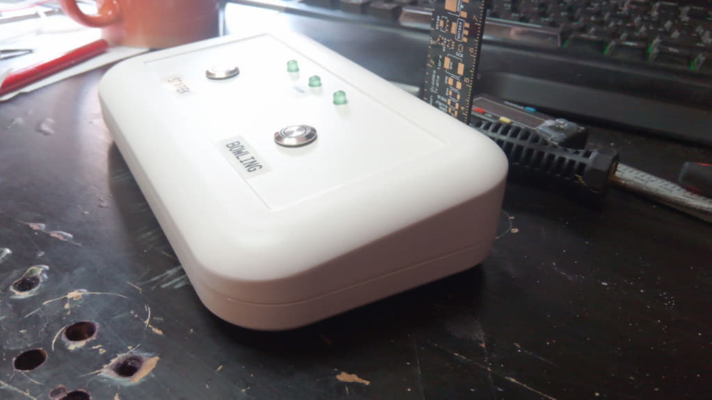
Again, it was so fast development so I do not have photos of the station unit. This is the master unit (kitchen) the only difference is in the number of buttons and LED. The master unit got two buttons (one for each restaurant) and three LEDs ( 1. restaurant status, power on LED, 2. restaurant status). The station unit got only one button and two LEDs.
The system is now working for almost three years in everyday use without problems. It turned out to be a wise decision to use the vandal-proof outdoor buttons. After all the use, all units are quite beaten but the buttons work still ok. The only problem with these buttons was their metal construction, and because the other parts are plastic, the static discharge on the button always restart the ESP, because the only path to the ground was by GPIO wires. It was easily fixed by grounding the button body to the negative input of the PSU.


